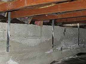
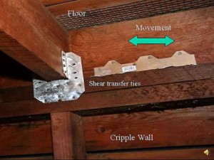
The following are examples of improper retrofit methods commonly performed by well-meaning but under-qualified personnel. Some of the photos have been provided by concerned home inspectors. These procedures should never be part of an earthquake retrofit. The comments in quotes are those of Thor Matteson, SE, our consulting Structural Engineer (www.shearwalls.com).
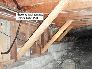 This illustration shows diagonal wood posts bolted to the floor framing.
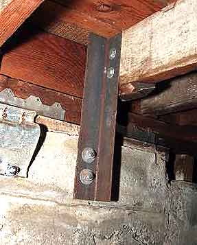 This vertical piece of angle-iron has been bolted into the foundation and to the floor framing.
 apart the concrete. While there are cases that angle-irons could be effective, in the majority of houses it is impossible to use them cost efficiently.”
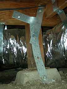
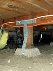 This photo shows two metal straps connecting the beam, post, and concrete pier. It is difficult from the photograph to see there are two straps here. The strap at the top is T-shape vertical stem of the “T” is extended downward with an additional straight strap to the concrete foundation pier.
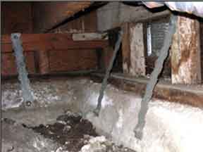 Each of these three straps is connected with a single bolt to the foundation.
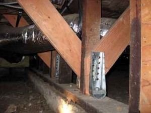 This is a Simpson PHD hold down. This will keep the post from lifting up off the mudsill and foundation, but earthquakes do not cause this to happen. The purpose of hold downs is to keep plywood shear walls from tipping over. The diagonal braces on this post will perform in a manner similar to Example 1 at the top of this page.
 This installation is also made of two straps and is similar to Example 3, only the “T” strap is turned sideways because a block obstructed its installation.
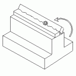
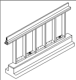 The “mudsill” is the wood member that bolts to the concrete foundation and supports almost all the weight of the house. Plywood shear walls must connect to the mudsill. The “Nailed Blocking Method” is used almost exclusively throughout the Bay Area. This is an untested method, and no one knows how well it will work. Other methods of making this connection are much more effective. Left is an illustration of how the Nailed Blocking Method is constructed. 2″x4″ blocks are nailed into the mudsill between studs. The nails often split the blocks. (See Examples 10 and 11) Bolts penetrate through the blocks and mudsill. Plywood is then nailed into the blocks and this attaches the plywood to the mudsill.
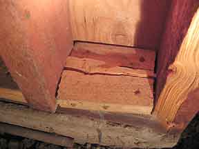 The plywood on the other side of this wall is nailed to the short block. Short blocks tend to split very easily—when this happens, the strength of a block is severely compromised. Plywood on many retrofit shear walls covers blocks that look just like this one. This is why, when the Nailed Blocking Method is used, it is very important for building departments to inspect the framing before the plywood is installed.
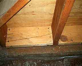 This is a longer block that has split. Often contractors switch to much thinner nails to prevent the block from splitting. Unless color-coded, it is impossible to distinguish nail size from just the head of the nail.
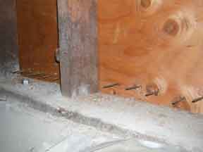 The nails coming through the plywood from the other side were supposed to be driven into blocks of wood that sit on and are attached to the mudsill with nails. When seen from the other side, i.e. the side the building inspector would see, this installation would look like it had been nailed into blocks.
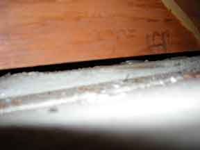 This photo is a close-up showing the bottom edge of a piece of plywood that is supposed to be part of a shear wall. This piece of plywood was nailed to the wall studs, without installing any blocks at all.
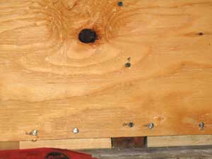 In this photo, you see that the blocks were installed, however the plywood sheet is too short. As a result, the nails along the bottom edge of the ply are not positioned as they should be along the horizontal center line of the block.
Also at question here, is why blocks were used at all when the studs “should” align with the sill plate. The proper size sheet of plywood should be be nailed directly to the sillplate eliminating a lot of unnecessary labour. If the studs don’t align very closely, then blocks should be used.
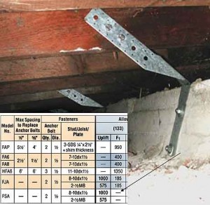 This is a Simpson “FSA” strap. The table, inset from the manufacturer’s catalog, shows that the strap does not resist earthquake forces but only uplift forces (the arrow points to a dash where a value would be if this strap could resist lateral forces generated by earthquakes). The dash here means this hardware has zero resistance to earthquake forces. These straps were bent into an “L” shape before installation.
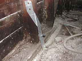 This is the same piece of hardware as shown in Example 13, just not bent into an “L”.
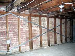 A few years ago, one city recommended bracing cripple walls with “plumber’s tape.” Plumbers tape is flimsy metal strapping used to suspend pipes underneath floor framing or attach water heaters to a wall—it is not designed to use in this way and will do practically nothing to resist earthquakes. A plywood shear wall should have been built here.
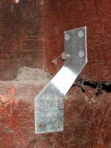 This is a Simpson “H3” (left), which is primarily intended to resist wind uplift from hurricanes, not side-to-side forces generated by earthquakes. It has minimal ability to resist such earthquake forces. It is also supposed to be installed with nails, not screws—and the hole at the bottom left is missing a connector all together.
The Simpson “H10” and Simpson “L90”, both shown here (right), can resist approximately four and six times, respectively, the amount of side-to-side force as the Simpson “H3”. With modern tools it is just as fast and easy to install these far more effective connectors.
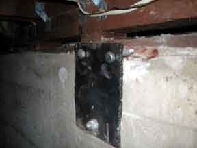 Note the gap between the steel plate and the wood mudsill. In this situation the bolts will bend and eventually be torn out of the mudsill. To keep the upper bolts from bending, a continuous piece of lumber or plywood needs to fill the gap and be attached to the mudsill with nails or screws that have the same total strength as the lag bolts. The lag bolts then need to be driven through the metal plate and into the piece of wood. When this is done, nails in the piece of lumber or plywood keep this piece of lumber from sliding on the mudsill. The lag bolts keep the piece of lumber or plywood from sliding along the inner edge of the plates.
 When the mudsill slides on the foundation, as in an earthquake, the metal plate would spin around the single bolt at the bottom of the plate like a propeller. This rotation will cause the bolts to push up and break the mudsill.
It is hoped that these examples of poor retrofit work impress upon you the need to check the work (that means YOU should crawl under your house) after a contractor has finished your retrofit but BEFORE you pay him.
